
Piezo Actuators - Displacement and Force Behavior
Nonlinear Displacement Behavior of Piezoceramics
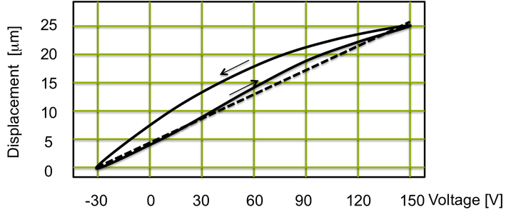
Real piezoelectric actuators exhibit divergent behaviour from pure linear constitutive equations. The used piezoceramic materials y show nonlinearity and hysteresis. Also, time- and temperature dependent effects are present. All these effects can be controlled by proper electronics. In closed-loop operation with feedback of displacement / strain measurement the hysteresis of the actuator can be well reduced.
An illustration of displacement of a piezoceramic material versus applied voltage for a piezo actuator stack, is shown in next figure. The hysteresis of the piezo stack actuator is indicated. With position control the hysteresis will effectively be reduced (dotted line).
Active Strain Performance of Piezoceramics
The active strain of standard actuators is 0.1% strain in unipolar driving mode (the voltage applied to the – and + terminals is ramped up form zero to the maximum positive value) and 0.14% in bipolar mode (the voltage applied between the – and + terminal is ramped between the allowed negative -30V to the most positive value 150 V). The strain depends on the pre-stress level. Appropriate pre-stress level increases the strain performance of the actuator.
Lateral contraction. The poisson ratio of the piezoelectric actuator material is about 0.3. Thus, the elongation of a piezo in field direction (the stack axis) is associated with 30% contraction in perpendicular direction. In other words, a transversal contraction occurs. The phenomena of transversal contraction cause tensile stresses in the interfaces of the stack. It generally require special consideration in the design of actuator mechanism. Actuators from Piezotechnik are specially designed to manage this mechanism. For that, the layer thicknesses increase toward the stack ends. By this measure, the internal electrical field is reduced at the stack end and the stress in the interfaces is effectively reduced.
Young´s modulus. The modulus of piezo materials is in the range of 30 to 60 GPa. The elastic modulus depends on the electrical boundary condition, as electro-mechanical coupling is effective. The effective modulus in an electrically open state is higher than that of a short-circuited state.
Generative Stress (Blocking Force Capability) of Piezo Actuators
The generated stress sigma is Young‘s modulus Y x active strain S.
sigma = Y S
The stress generation capability of piezo stacks is in the order of 3.500 N (unipolar) and 5.000 N (semi-bipolar) per cm2 stack base area. This is a large value for any actuator principle! The high stress capability is highly valuable for the design of actuator application. Generally, piezo stacks deliver strong forces, fast reaction and be used for ultra- precise positioning. The actuators are mechanically stiff elements. One can only transfer this capability into large active forces effectively, if the load at the interfaces to the actuator represents a mechanically stiff element.
Force Generation Behavior of Piezo Actuator Elements
As described the electric field cause mechanical stress which induce a deformation of the actuator body. The generative force Fg is the product of actuator area A and the piezoelectric stress sigma:
F = A sigma
The generated stress s is proportional to the piezoelectric constant d, which is a material property, and the applied electrical voltage. The maximum generative force is provided in the actuator specification. The proper actuator size can be selected by choosing the actuator base area.
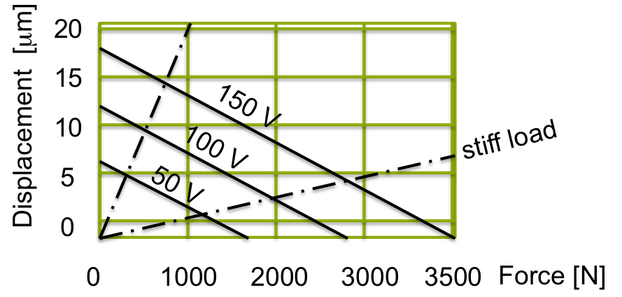
It is important to consider that piezo actuators are solid bodies and feature much higher mechanical stiffness than any other actuator of same size. In mechanical equilibrium the generative force is equal the sum of the useful load force and the internal elastic force which is associated with the actuator deformation. This means that the useful force reduces linearly with displacement X. X0 denotes the free displacement (no lad situation).
Fload = Fg (1-X)/X0
An illustration of the force versus displacement output of a piezoelectric actuator with various applied voltages is shown in the next figure.
Creep and Drift of Piezo Actuator Elements
Piezo actuation effect is partly subjected to time-dependent phenomena of the orientation of dipoles in the material. After change of voltage the stack immediately react and a force is generated by the interaction of the field and the dipoles of the piezo material. The piezo stack deforms and produces useful displacement. In analogy to magnetic materials the the microscopic structure of piezo comprises electric dipoles that are coupled and manifest in domains. The orientation of the dipole of the domains is influenced by electric field and mechanical stress. These couplings cause secondary effects. Afterward fast settling of the electric field cause further reorientation of the dipoles and the stack creeps slowly until reaching equilibrium. Of course, these effects are much smaller than the immediate reaction. Those effects can be corrected by feed-back of position.
Unipolar and Quasi-Bipolar Operation of Piezo Stacks
Piezotechnics Actuators are designed for unipolar as well as bipolar voltage operation. The standard operation is from 0 to 150 V (unipolar). Quasi-bipolar operation from -30 V to +150 V brings the advantage of up to 40% higher displacement.
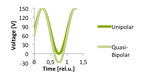
Quasi-bipolar operation is an extremely powerful method to enhance actuator performance. Piezotechnik actuators have the necessary characteristics the quasi-bipolar operation requires. Nevertheless, it may be noted, that this that this driving method increases the specific mechanical and electrical loads of the material. Also, with the power conversion throughput losses increase.