
Piezo Actuator Stack - The Fundamental Mechanical Load Cases
The linear constitutive equation for piezo stack actuator behavior describes a linear elastic material with the superimposed effect of electrically induced force, which is linear to the applied electrical field. Second, a piezo actuator represents a capacitor with the superimposed effect of induced charge linear with the applied force. In conclusion, piezo actuation is based on electrically controlled deformation of a solid body. When a voltage is applied to a piezoelelectric actuator piezoelectric forces are generated instantaneously inside the solid body, which deform it and move the load to reach mechanical equilibrium. This represents the background for strong and fast force generation of piezo stacks for precise control applications.
From the above noted equations, important load cases can be examined:
Piezo Actuator Stack - No Load - Free Stroke Case
The displacement X of a piezo actuator X is equal piezoelectric (charge) constant d x voltage U.
Multilayer actuators use a multitude of thin layers and the total achievable displacement is the value of the individual layer multiplied by the number of layers. The layer thickness is in the order of 100 um, voltages are 150 V and field strength is 1 – 2 kV/mm.
Piezo Actuator Stack - Mass Load - Constant Force Load Case
T = constant. The displacement X of the actuator does not change and is still equal piezoelectric (charge) constant times voltage d x U. The mass force statically deforms the actuator and the electrically controlled displacement is superimposed to this static deformation. This describes the behavior of a stack when external forces are much smaller than the blocking force.
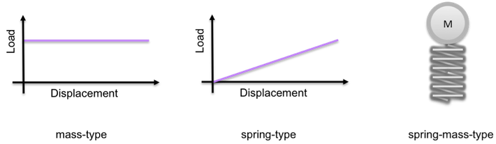
Piezo Actuator Stack - Spring Force Type Load Case
The displacement of the actuator is reduced by the ratio of stiffness of the
load spring kload and actuator ka.
X= X0 ka/(ka + kload)
(free displacement X0 = d U)
Piezo Stack - Blocked Actuator Stack - Blocking Force Case
The generated force is equal base area x piezoelectric constant d x electric field divided by compliance s.
Fb = A d E/s
Load Case - Abrupt application of Voltage at a Piezo Actuator Stack
If the voltage source is abruptly switched on or a very high voltage rate (faster than Volts per milliseconds) is applied to the piezo stack, the actuator will experience a step function excitation. The electric behaviour of the actuator is that of a capacitor and will pull large currents I form the amplifier to ramp up the voltage during rise time DT.
I = C dU/dt
If the amplifier is capable to provide high currents, the actuator will overshoot in this situation and internal tensile stress results. The actuator stack is in danger to be damaged if not sufficient measures are taken:
- First, current limiting is reliable method to reduce rise time and to avoid overshoot.
- Second, a pre-stress mechanism can be installed which compensate transient tensile stress amplitude.
Piezo Actuator Stack - Dynamics of an Actuator Stack which is Loaded by a Mass-Spring-Combination
In dynamic actuation mode periodic (sine, square waves) or non-periodic waveforms (e.g. compensation of disturbances in a feedback control loop) are applied to the actuator. In modern car engines high-pressure fuel injectors are used to spray very precisely fuel into the combustion chamber. Piezo is the superior actuator principle to control the injection process and superseded electromagnets. The piezo in a fuel injector is used to generate several fast pulses during each combustion cycle.
The dynamic response of a piezo actuator and connected mechanical load to the electrically controlled piezoelectric force is determined by masses, stiffness’s, and damping rates. The actuator itself represents a spring mass system with low damping rate. The low frequency response of that basic actuator system is given by the free stroke. At higher frequencies the stroke is limited by the inertia of the effective actuator mass. The realizable displacement of an actuator in sinusoidal operation is given by the equilibrium of the piezoelectric force and the force needed to accelerate the effective mass. The following equations illustrates the mechanical response quite below and beyond the mechanical resonance frequency fr:
a) f < fr X = d U
b) f > fr X = Fb / (mload (2 pi f)2)
Highly dynamic operation of a piezoelectric actuator results in high levels of mechanical (force x speed) and electrical power (voltage x current). Damping is effective in piezoelectric materials and in dynamic operation losses occurs with resulting heating of the material. Continuous dynamic operation can generate high losses and the piezo stack may rapidly heat up. Sufficient measures has be taken to avoid excessive temperatures:
· limit the amplitude (travel, voltage),
· limit frequency,
· limit the duration of operation, and
· adequate cooling.
Contact Piezotechnics if high power levels are required. Piezotechnics is experienced in highly dynamic actuation.