
Piezo Stack Under Constant Force
This case describes the situation, when the load force Fload is constant or varies negligibly with regard to the blocking force of the selected stack and is independent from the actuator displacement. This situation is given in case of
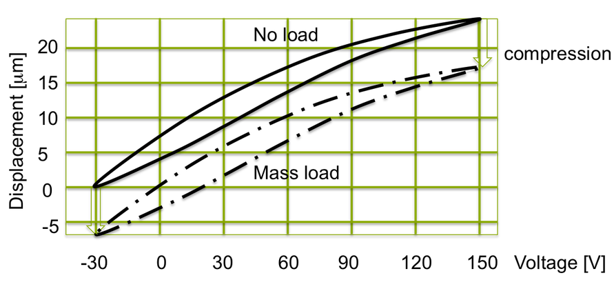
- Mass load, a mass is simply attached to the piezo.
- Constant pneumatic or hydraulic pressure, e.g. a cylinder is acting against the stack (of course, in perfect alignment of the force axis to the stack axis.)
- soft spring load which spring rate is much smaller than the actuator stiffness and preferably is already widely compressed.
Under constant compression force a piezo does not suffer the loss of its displacement capability. Within the acceptable load force given in data table of the stack, the actuator can provide full performance. This behaviour is shown in the next figure. A constant force also is quite positive with regard to structural stability as it provides compressive forces. This shall be limited to the recommended pre-stress-level which is maximum in the order of the generative force of the stack (equiv. to the blocking force capability of the individual stack).
Select the Right Piezo Stack Actuator
To select the right actuator you simply need to determine two key data:
- the maximum required displacement Xmax
- the maximum required force Fload.
In consequence of the constancy of the displacement in these load conditions, the actuator can be chosen by its two main performance data blocking force Fblock and free displacement X0 :
X0 = Xmax + margin (e.g. 20%)
Fblock = Fload + margin (e.g. 50%).
The load force shall not exceed the blocking force.Thus a margin of 50 - 100% is recommended.
Example for Selecting an Actuator Stack
A piezo actuator has to position a mass of 75 kg over a range of 35 mm. The required performance data are
-
- F load = 75 kg x 9,81 m s-2 = 736 N, and
- X0 = 35 mm.
A stack with base area of 5 x 5 mm2 generates 850 N and would be sufficient. A stack with a length of 40 mm delivers in unipolar mode 42 micro meter. This would provide a sufficient margin of 7 micro meter, which is 20% on top of the required displacement. Therefore, a stack 5 x 5 x 40 mm is a right choice. Dependent on the mechanical system design, a larger stack area e.g. 7 x 7 mm may be selected.
-
- Fb = 850 N
- X0 = 42 micro meter
- A = 5 x 5 mm2 (or 7x7 mm2 may be chosen)
- Height = 40 mm